Comtech EF Data UT-4514F Specifiche Pagina 26
- Pagina / 162
- Indice
- RISOLUZIONE PROBLEMI
- SEGNALIBRI
- UT-4500-A Series 1
- TABLE OF CONTENTS 5
- FIGURES 12
- PREFACE 15
- Metric Conversion 16
- Safety and Compliance 17
- Electrical Installation 17
- Operating Environment 17
- (2004/108/EC) 18
- Preface MN-UT4500A 19
- Warranty Policy 20
- Limitations of Warranty 20
- Exclusive Remedies 21
- Getting Help 22
- Contacting Comtech EF Data 22
- Chapter 1. INTRODUCTION 25
- 1.2 Functional Description 26
- 1.2.1 Applications 27
- 1.2.2 RF Signal Conversion 28
- 1.2.3 Monitor & Control 28
- 1.3 Upconverter Features 29
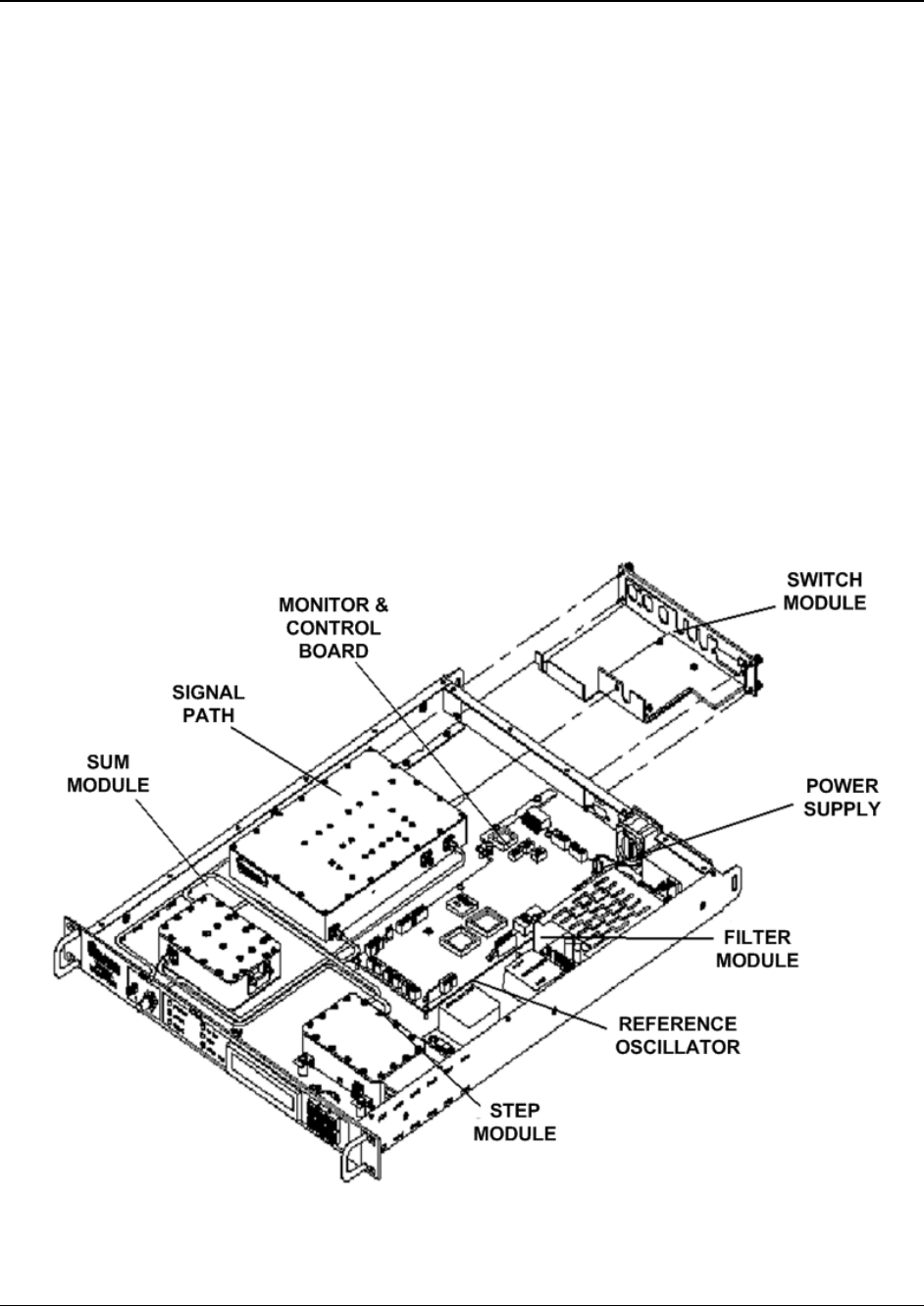
- 1.3.1 Physical Description 29
- 1.3.2 Dimensional Envelope 30
- 1.3.3.1 Front Panel 31
- 1.3.3.2 Rear Panel 31
- Introduction MN-UT4500A 32
- Chapter 2. INSTALLATION 43
- Installation MN-UT4500A 44
- 2.4 Connect External Cables 49
- Chapter 3. REAR PANEL 51
- CONNECTORS 51
- 3.3 Cable Connections 59
- Module (TSM-XX) 60
- Chapter 4. UPDATING FIRMWARE 63
- Chapter 5. FRONT PANEL 69
- OPERATION 69
- 5.1.2 LED Indicators 70
- 5.1.3 Keypad 71
- 5.2 2BOpening Screen 72
- 5.3 Main Menu 72
- 5.3.1.1 CONFIG: OUTPUT 73
- ▲ ▼ arrow keys 75
- ▲ ▼ arrow keys to edit 76
- 5.3.1.3 CONFIG: REDUNDANCY 77
- 5.3.1.5 CONFIG: COLDSTART 79
- 5.3.2 MONITOR 80
- 5.3.3 FAULTS 80
- 5.3.3.1 FAULTS: CURRENT 80
- 5.3.4 PRE-SELECTS 82
- 5.3.4.1 PRE-SELECTS: LOAD 82
- 5.3.4.3 PRE-SELECTS: CLEAR 83
- 5.3.5 UTILITY 83
- 5.3.5.5 UTILITY: SLOPE 85
- 5.3.5.6 UTILITY: LAMP-TEST 85
- 5.3.5.7 UTILITY: FIRMWARE 85
- Chapter 6. ETHERNET-BASED 87
- REMOTE PRODUCT 87
- MANAGEMENT 87
- 6.2 SNMP Interface 88
- 6.2.3 SNMP Traps 89
- 6.3 Telnet Interface 90
- 6.4.2 User Login 92
- 6.4.3.1 Navigation 93
- 6.4.3.2 Page Sections 93
- 6.4.3.3 Action Buttons 93
- 6.4.3.4 Drop-down lists 94
- 6.4.3.5 Text or Data Entry 94
- 6.4.5.1 Home Pages 95
- 6.4.5.1.1 Home 95
- 6.4.5.1.2 Home 96
- 6.4.5.1.3 Home 97
- 6.4.5.2 Admin Pages 98
- 6.4.5.2.1 Admin 98
- Webpage Timeout 99
- 6.4.5.2.2 Admin 100
- 6.4.5.3 Config Pages 101
- 6.4.5.3.2 Config 103
- Pre-Selects 104
- Load Pre-Select 104
- 6.4.5.3.4 Config 105
- Perform Soft Reboot 106
- Part Number (read-only) 106
- 6.4.5.4 Status Pages 108
- 6.4.5.4.1 Status 108
- 6.4.5.4.2 Status 109
- Appendix A. REMOTE CONTROL 111
- A.2.2 TIA/EIA-232 (RS-232) 112
- A.2.3 Ethernet (100BASE-TX) 112
- A.3 Access Methods 112
- A.3.1 Direct Access 112
- A.3.2 Indirect Access 113
- A.4 Addresses 113
- A.4.1 Physical Address 113
- A.4.2 Virtual Address 113
- Appendix A MN-UT4500A 114
- A.6.4 Confirmation Response 116
- A.6.5 Error Response 116
- A.6.6 End of Message 116
- A.6.6.1 Command Ending 116
- A.6.6.2 Response Ending 116
- A.7.1 Utility Commands 117
- A.7.1.1 Time 117
- A.7.1.2 Date 117
- A.7.1.7 IP Address 119
- A.7.1.8 IP Gateway 119
- A.7.1.9 Physical Address 119
- A.7.1.10 Baud Rate 120
- A.7.1.11 LCD Contrast 120
- A.7.1.12 LCD Brightness 120
- A.7.1.13 Screen Saver Mode 120
- A.7.1.15 VFD Brightness 121
- A.7.1.18 Equipment Type 122
- A.7.1.19 Part Number 122
- A.7.1.22 Firmware Image 123
- A.7.1.24 Force Reboot 124
- A.7.2.1 Frequency 125
- A.7.2.2 Attenuator 125
- A.7.2.3 Cold Start 125
- A.7.2.4 Mute 126
- A.7.2.5 Carrier Mute Mode 126
- A.7.2.6 Redundant Mute Mode 126
- A.7.2.7 Auto Fault Recovery 127
- A.7.2.8 Program Preset 127
- A.7.2.9 Display All Presets 127
- A.7.3 Modes 129
- A.7.3.1 Redundant Mode 129
- A.7.3.3 Backup Mode 130
- A.7.4 Status Commands 131
- A.7.4.2 Maintenance Status 131
- A.7.4.3 Utility Status 132
- A.7.4.4 Alarm Status 132
- A.7.5 Stored Alarms 136
- A.7.5.1 Total Stored Alarms 136
- A.7.5.3 List All Alarms 136
- A.7.6 Error Processing 137
- A.7.6.1 General Errors 137
- A.7.6.3 Mode Errors 137
- A.7.6.4 Time-Outs 137
- A.7.7 Command Summaries 138
- Appendix B. REDUNDANT 141
- SYSTEM OPERATION 141
- B.2 Backup Upconverter 142
- B.2.1 High Speed Bus (HSB) 142
- B.2.2 Detachable Modules 142
- Appendix B MN-UT4500A 143
- TSM-XX Installed 145
- Interface 153
- B.4.3 Offset Adjustment 154
- Appendix C. MAINTENANCE AND 157
- TROUBLESHOOTING 157
- Appendix C MN-UT4500A 158
- C.2.3.3 RF Converter Module 159
- C.2.3.7 Temperature Fault 159
- C.2.4 Converter I/O Modules 160
- C.3 Spares 160
- METRIC CONVERSIONS 161
- Units of Length 161
- Temperature Conversions 161
- Units of Weight 161
- 480 • 333 • 2200 PHONE 162
- • 333 • 2161 FAX 162
Prodotti e manuali riguardandi no Comtech EF Data UT-4514F
 (14 pagine)
(88 pagine)
(4 pagine)
(38 pagine)
(14 pagine)
(88 pagine)
(4 pagine)
(38 pagine)
© 2020, manymanuals.it. Tutti i diritti riservati | 0.017 s |
 Manymanuals.com
 Manymanuals.de
 Manymanuals.fr
 Manymanuals.it
 Manymanuals.pl
 Manymanuals.cz
 Manymanuals.es
 Manymanuals-pt.com
Commenti su questo manuale